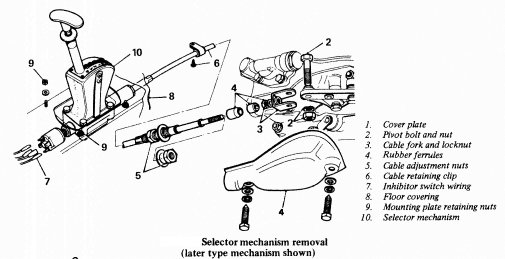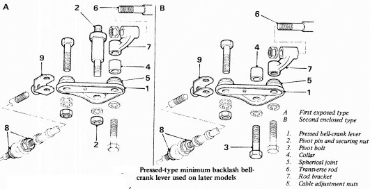
Pull back the rubber sleeve (early models) or remove the cover plate (later models) from the bell-crank lever on the transmission unit. On models with the original forged-type bell-crank lever, extract the split pin and remove the clevis pin securing the selector cable fork to the bell-crank arm. On units fitted with later pressed-type bell-crank lever, the cable fork is secured to the lever by a nut and bolt instead of a clevis pin.
Slacken the locknut at the selector cable fork and remove fork, locknut, both rubber ferrules and the sleeve (where fitted) from the cable. Remove cable front adjusting nut from the outer cable arid pull the cable clear of the bracket or abutment on the transmission.
Remove the screw securing the cable retaining clip to the floor panel, and pull the cable clear of the transmission unit.
Disconnect the wiring from the start-inhibitor switch at the rear of the selector lever housing, working from under the car. Note the respective position of the leads.
From inside the car, pull back the front floor covering.
Remove the four nuts securing the selector mechanism mounting plate to the floor panel and remove the selector mechanism, with the cable attached, from the car. Note that a joint washer is fitted between the mounting plate and the floor panel.
On early models the selector housing is secured directly to the floor by four bolts and in this case the assembly is removed by carefully pulling the cables through the rubber dust excluder.
a) If seizure of the bell-crank lever has occurred on models fitted with the original forged-type bell-crank lever due to over-tightening of the pivot pin nut, replace the pivot pin and distance tube with a modified pivot pin having a shoulder.
b) If backlash is excessive on the original forged-type bell-crank lever, replace with the later pressed-type minimum backlash bell-crank lever assembly.

Remove the bellcrank lever and its pivot pin, then the front cover and the transverse rod. Fit modified type of pivot pin and clevis, non-adjustable transverse rod and pressed-type bell-crank lever. Refit the front cover.
c) If pressed-type bell-crank lever assembly has been fitted in place of the original forged-type lever, reverse position of the selector lever indicator gate should be modified to ensure that the selector valve detent is fully engaged when the selector lever is moved into reverse position. Unscrew the handle from the gear selector lever, then remove four screws securing the indicator gate to the quadrant. File a radius 1/16 in (1.6 mm) deep in the end of the gate as shown in
 .Refit the gate and lever handle.
d) If slip or loss of drive occurs in reverse gear after a replacement transmission with pressed-type minimum backlash bell-crank lever has been fitted, check whether the indicator gate has been modified as described above. If not, and adjusting the selector cable as described under 'Adjustments' heading fails to remedy the fault, then the gate modification should be carried out.
e) When installation of the selector housing and cable is complete, adjust the cable, transverse rod (where applicable) and start-inhibitor switch as detailed under 'Adjustments' heading previously.
2. Release the reverse return spring from the underside of the housing. Remove four bolts securing the quadrant to the housing and lift off the quadrant and lever assembly. Lift off the mounting plate and joint washer (where fitted).
3. Unscrew the outer cable securing nut from the front of the housing and withdraw the cable and lever plunger from the housing. Slacken the inner cable locknut and screw the plunger off the cable end.
a) Lubricate all parts with grease prior to reassembly.
b) When reassembling the quadrant and lever assembly to the housing, ensure that the gear lever engages correctly with the lever plunger. The slot in the plunger is relieved on one side only and this side must be positioned upwards so that it engages with the lever.